Important
This educational article presents how to apply the electrical safety tests linked to IEC 60601-1. It can never replace the medical-device service manual written by the manufacturer, which remains the reference for every verification and electrical-safety procedure, together with the user manual of your electrical safety tester.
Information and liability clause
The tests described below are based on the user documentation of Fluke electrical safety testers and on the OneQA tool. They are provided for information and training only and are not intended to replace, in whole or in part, the user manual or the official technical documentation of your electrical safety tester, whatever its brand or model.
Each user must strictly follow the instructions, warnings and requirements of the manufacturer of the instrument in use, in particular regarding operating conditions, safety, servicing and maintenance.
AFIACARE accepts no liability, of any kind, for direct or indirect material or non-material damage arising in particular from:
- use that does not comply with the manufacturer’s recommendations or the applicable standards
- an incorrect interpretation of the tests or results
- a change to procedures, parameters or configurations not validated by the manufacturer
- a lack of qualification or supervision of the operator
Using the tests described implies the user’s express acceptance of this clause and the assumption of the risks inherent in the operations performed. Any reproduction, adaptation or distribution of the tests must be carried out under the responsibility of the organisation that implements them and in compliance with the standards and regulations in force.
1. Why is IEC 60601-1 so important?
IEC 60601-1 is the cornerstone of design and type testing for medical devices. It defines the basic safety requirements that protect the patient from electric shock, fire and mechanical hazards.
The human body, especially in a hospital, is extremely vulnerable. The standard rests on a simple principle: the patient must never be exposed to a dangerous current, even if a first failure occurs in the device.
- Physiological effect: at 50/60 Hz, a current of only 10 mA can cause a muscle contraction (“let-go current”), and a few microamperes are enough to trigger cardiac fibrillation if the current is applied directly to the heart (microshock).
2. Key concepts: classes, types and isolation
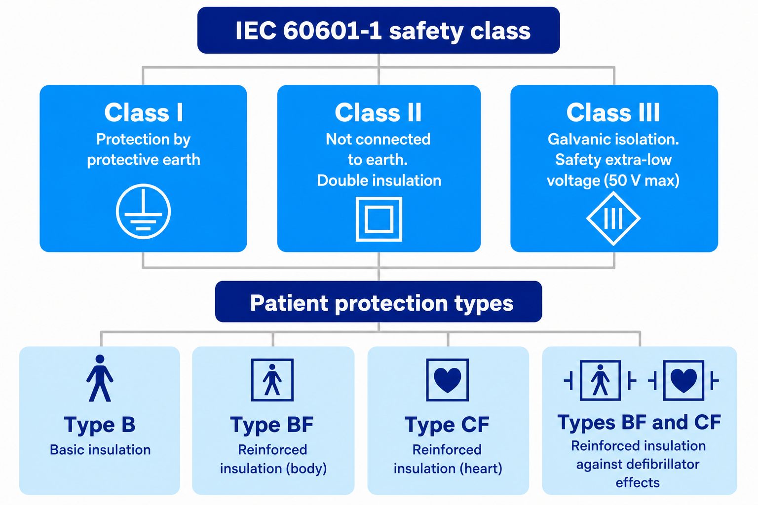
Before looking at the tests, it is essential to master the basics of electrical safety testing on a medical device. The diagram summarises the classification and the applied-part types.
The classification of equipment defines its level of protection against electric shock, while the applied-part category specifies the degree of patient contact and the isolation required under NF EN 60601-1.
3. Tests under IEC 60601-1 — 3rd edition
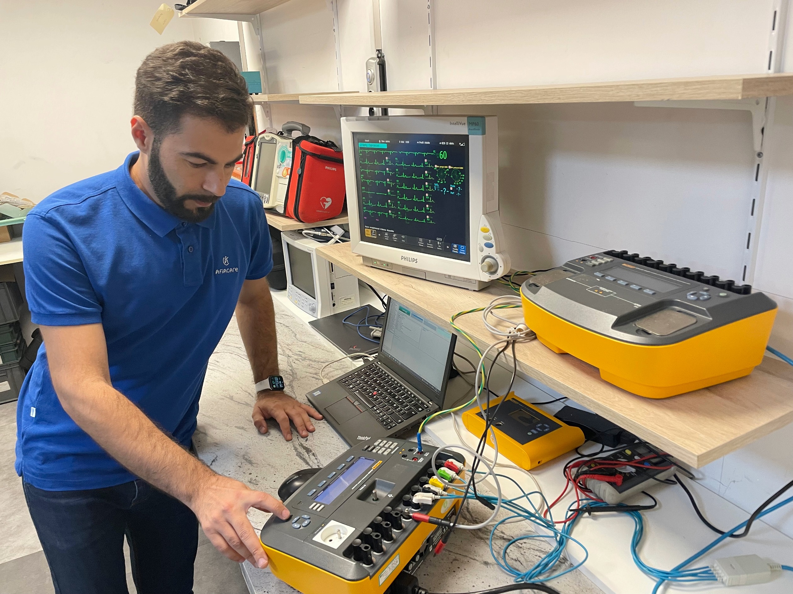
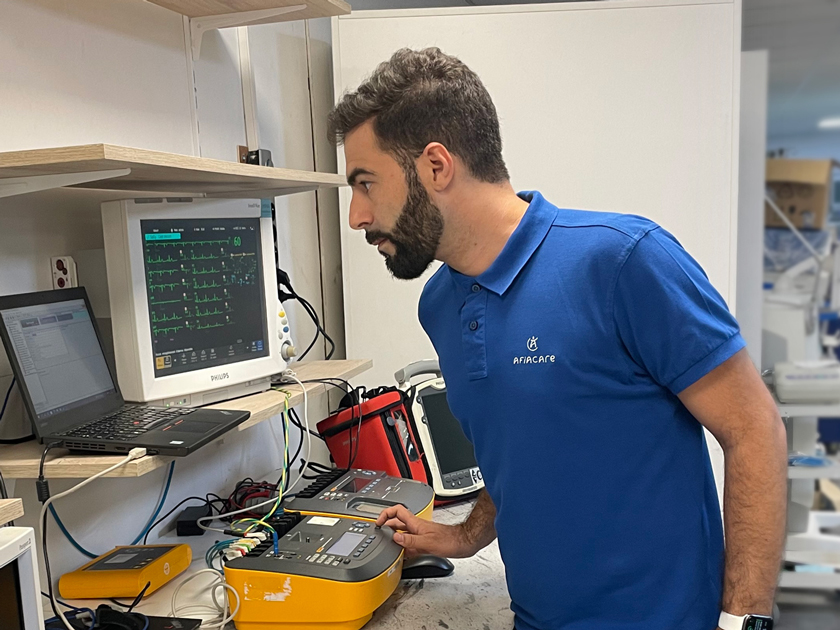
AFIACARE has chosen Fluke electrical safety testers and has automated maintenance tests with OneQA, which now replaces Fluke’s Ansur software for driving Fluke testers and managing maintenance processes.
The tests below are based on the user documentation of Fluke electrical safety testers and on OneQA. They can never replace the user manual of your electrical safety tester (whatever its brand or model), in accordance with the information and liability clause at the beginning of this article.
3.1 Measurement designations according to the standard
| IEC 60601-1 (FR) | IEC 60601-1 (EN) |
|---|---|
| Mains voltage | Mains voltage |
| Protective earth resistance | Protective earth resistance |
| Insulation resistance | Insulation resistance |
| Earth leakage current | Earth leakage current |
| Touch current (enclosure leakage) | Touch current (Enclosure leakage) |
| Patient leakage current | Patient leakage current |
| Patient auxiliary current | Patient auxiliary current |
| Mains on applied part (MAP) | Mains on applied part (MAP) |
1. Protective earth resistance (earthbond)
- Purpose: check that the earth conductor can carry a fault current without melting.
- Specificity: unlike in-service maintenance (200 mA), 60601-1 often requires a test at 25 A (or 1.5 times the rated current) for 5 to 10 seconds. Resistance must be ≤ 0.1 Ω (without the cable) or 0.2 Ω (with a detachable cable).
2. Earth leakage current
- Measures the current flowing in the protective earth conductor.
- Limit (normal condition): 500 µA (0.5 mA).
3. Enclosure / touch leakage current
- Measures the current a person would touch when placing a hand on the chassis.
- Limit (normal condition): 100 µA (0.1 mA).
4. Patient leakage current
- The most critical test. It measures the current flowing between the applied parts and earth.
- Strict Type CF requirement: only 10 µA in normal condition.
4. Single fault condition (SFC)
The philosophy of IEC 60601-1 is resilience. The device is tested not only in normal operation, but also by simulating electrical faults:
- Open neutral: break of the neutral conductor.
- Open earth: break of the earth conductor (the most common test for Class I).
- Reversed polarity: phase/neutral reversal.
- Mains on applied part: 110 % of mains voltage is applied to the ECG leads (for example) to check that no dangerous leakage crosses the insulation toward the patient.
Focus on current flows
- Patient leakage current: an unintentional current from an insulation fault. It must be almost zero to avoid fibrillation.
- Patient auxiliary current: an intentional current (e.g. measurement electrodes). It is part of the design but strictly limited to avoid any physiological effect.
Summary of limits — A. Patient leakage current (AC)
| Test condition | Maximum limit | Meaning |
|---|---|---|
| Normal polarity | 100 µA AC | Ideal operation. |
| Open neutral or open earth | 500 µA AC | Single fault (SFC). |
| Reversed polarity | 100 µA AC | Reversed connection. |
| Reversal + fault (SFC) | 500 µA AC | Combination of faults. |
B. Patient leakage current (DC)
- Normal / reversed: 100 µA DC.
- Fault (selective): 500 µA DC.
C. Patient auxiliary current (AC/DC)
- General limit: 500 µA (checks that the measurement current remains safe).
5. Limit summary (technician dashboard)
| Test type | Condition | Type B | Type BF | Type CF |
|---|---|---|---|---|
| Patient leakage (AC) | Normal | 100 µA | 100 µA | 10 µA |
| Patient leakage (AC) | Fault (SFC) | 500 µA | 500 µA | 50 µA |
| Patient leakage (DC) | Normal | 10 µA | 10 µA | 10 µA |
| Mains on applied part | Fault (SFC) | 5000 µA | 5000 µA | 50 µA |
6. Operational summary for the tests
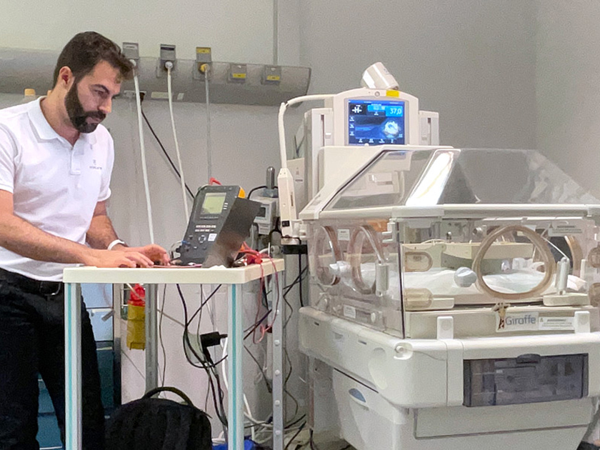
To perform a test that complies with IEC 60601-1 using an analyser such as a Fluke ESA715 or a Rigel 601:
- Measurement circuit: use the standardised “MD” (measuring device) that simulates the impedance of the human body (1000 Ω).
- Visual inspection: check the markings (B, BF, CF symbols) and the integrity of the enclosure.
- Test sequence:
- earth (if Class I)
- earth / enclosure leakage
- patient leakage (in every polarity and fault combination)
- Report: document every single-fault-condition value, because that is where isolations are truly put to the test.
Educational guide: why these measurements?
- Leakage current (“the parasite”): an electrical “leak”. For a fragile patient (Type CF), a leak above 50 µA can be fatal. The test checks that it remains imperceptible.
- Auxiliary current (“the messenger”): the signal sent to obtain a reading (e.g. respiratory rate). The test checks that it is not too strong for the body.
- Fault tests (“the crash test”): in real life a socket is often miswired or a conductor comes loose. The test proves that the device still protects the patient when the electrical installation fails.
Operational summary for the technician
- Visual inspection: 50 % of problems (cables, enclosures, symbols) are resolved here.
- Earth continuity: inject 25 A (design) to test the mechanical robustness of the earth conductor (≤ 0.2 Ω).
- Body model: always use an analyser (Fluke ESA715, Rigel) that simulates human impedance (1 kΩ).
- Technical file: compliance with these limits is required for CE marking.
Conclusion
IEC 60601-1 ensures that medical technology remains an aid and not a hazard. Mastering isolation tests and leakage currents is the last line of defence for patient safety.