Important
This educational article presents how to apply the electrical safety tests linked to IEC 62353. It can never replace the medical-device service manual written by the manufacturer, which remains the reference for every verification and safety procedure, together with the user manual of your electrical safety tester.
Information and liability clause
The tests described below are based on the user documentation of Fluke electrical safety testers and on the OneQA tool. They are provided for information and training only and are not intended to replace, in whole or in part, the user manual or the official technical documentation of your electrical safety tester, whatever its brand or model.
Each user must strictly follow the instructions, warnings and requirements of the manufacturer of the instrument in use. AFIACARE accepts no liability for damage arising from non-compliant use, an incorrect interpretation of the results, or a lack of operator qualification.
From network theory to clinical validation
IEC 62353 is not simply a “lighter” version of the design standard (60601-1). It is an operational tool designed to ensure that, throughout its life, a medical electrical (ME) device remains safe for the patient and the user — at incoming inspection, during preventive maintenance or after a repair.
1. Current analysis: what must be measured
The standard distinguishes two critical leakage-current paths:
- Device leakage: measures the total current escaping from the enclosure to earth.
- Applied-part leakage: measures the current at sensors or cables in direct contact with the patient (e.g. ECG electrodes).
Critical field errors
| Error | Consequence |
|---|---|
| Forgetting to disconnect earth | Currents read as almost zero (the current returns through the earth conductor instead of the analyser). |
| Test on an IT-M network (OR / ICU) | Artificially low currents because of the isolation transformer. |
2. Measurement methods: the right choice for the installation
| Method | Ideal use | Constraints |
|---|---|---|
| Direct | Mobile devices, isolable earth. | The most accurate. Requires the earth to be interrupted. |
| Differential | Fixed devices (earth cannot be isolated). | Measures the difference between phase and neutral. |
| Alternative | IT-M networks (operating theatres) or maximum operator safety. | Impossible if the device has an electronic switch. |
3. Influence of the electrical network (neutral system)
The hospital electrical environment changes the real value of the currents. A technician must adapt the calculations:
- TN-S / TT networks (230 V with neutral): direct reading, no correction needed.
- Phase-to-phase networks (230 V without neutral): voltages to earth are reduced. Action: multiply the measured value by √3 before comparing it with the standard limits.
- IT-M network (Group II rooms): the isolation transformer “crushes” leakage currents.
- Solution: use the alternative method (independent of mains voltage) or power the device from a socket outside the IT-M zone (radiology outlet or extension lead).
4. Test protocols and fault conditions
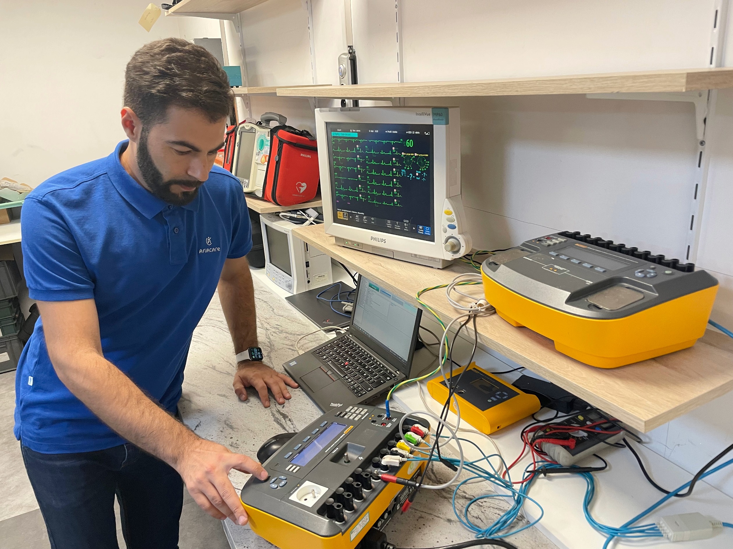
To simulate the worst-case failures, the analyser (e.g. Fluke ESA715 or Rigel 288) varies the conditions:
A. Basic conditions
- Reversed polarity: simulates a phase/neutral reversal in the wall socket.
- Open neutral: simulates a break of the neutral conductor in the mains cable.
- Open earth: simulates the loss of earth protection.
A distinction must be made between leakage current (accidental) and auxiliary current (intentional, for the physiological measurement).
B. Safety limits (patient and auxiliary)
| Test | Condition | AC limit | DC limit |
|---|---|---|---|
| Patient leakage | Normal polarity | 100 µA | 10 µA |
| Patient leakage | Open earth / open neutral | 500 µA | 50 µA |
| Auxiliary current | Normal | Depends on the device type (ECG, EEG, etc.) | — |
5. Tests under IEC 62353
AFIACARE has chosen Fluke electrical safety testers and has automated maintenance tests with OneQA, which now replaces Fluke’s Ansur software for driving Fluke testers and managing maintenance processes.
The tests below are based on the user documentation of Fluke electrical safety testers and on OneQA. They can never replace the user manual of your electrical safety tester (whatever its brand or model), in accordance with the information and liability clause at the beginning of this article.
5.1 Measurement designations according to the standard
| IEC 62353 (FR) | IEC 62353 (EN) |
|---|---|
| Tension secteur | Mains voltage |
| Résistance de la terre de protection | Protective earth resistance |
| Résistance d’isolement | Insulation resistance |
| Courant de fuite de l’appareil | Equipment leakage current |
| Courant de fuite patient | Patient leakage current |
| Fuite de la partie appliquée (tension secteur) | Applied part leakage (Mains voltage) |
6. Operational summary: your checklist
Before releasing a device, follow this logical flow:
- Visual inspection: cable condition, cleanliness of ports, enclosure integrity (50 % of faults are found here).
- Earth resistance: check that R ≤ 0.3 Ω (for a 3 m cable).
- Choice of method:
- mobile device + socket → direct
- operating theatre → alternative (if possible) or test outside the room
- Normalisation: if the mains voltage U₀ ≠ 230 V, apply the correction factor: corrected value = measured value × (230 / U₀).
- Signature: record the report with the serial number of the analyser used.